Preparing the lab
Gantry position changes
Changing the MEG measurement position
To ensure that the gantry is prevented from falling down from lower or upper seated measurement positions under any circumstances it is equipped with two completely separate and parallel support mechanisms. The lifting motor and the safety latches on both sides can alone withstand a four-fold overload. To ensure safety even in case of a fault, the gantry must always be left in one of the three secured positions.
- The measurement position must not be changed while there is somebody under the probe unit.
- Do not let any person under the probe unit unless the green OK light is lit on the position indicator display.
- Remove the bed or chair and other possible accessories from around the probe unit before changing the measurement position
- Care should be exercised to prevent limbs, fingers, or toes being left between moving parts of the chair or bed and probe unit or doorway.
The probe unit can be set to three fixed positions: lower and upper seated positions for measurements with the chair and supine position for measurements with the bed
- The measurement array inside the helmet shaped, lower part of the probe unit is tilted from horizontal by 60° or 68° in the lower and upper seated positions, respectively, whilst it is horizontal (0°) in the supine position.
Position indicator display
The operation of the probe unit lifting mechanism can be monitored with the help of the position indicator display located on the wall behind the probe unit.

Indicators of the display are the following:
Green light "OK": Probe unit measurement position is secured (supine, lower seated, or upper seated). This is the normal case. Never place a patient under the probe unit except when green OK light is lit.
Amber light "Tension": Probe unit position is not secured, and weight of the Dewar cradle tensions the ropes of the lifting mechanism. This is normal during up/down movement. When tension of the ropes is released (and light goes off), downward movement of the motor stops.
Amber light "Limit": Dewar cradle has reached the upper limit of the upward movement and motor stops. Only downward movement is possible. This is normal during up/down movement.
Red light "Fault": Abnormal condition due to malfunctioning of the lifting mechanism and/or the fiber optic sensors monitoring the position. Contact service representative.
Signal check
Sensor Tuning
For detailed instructions to signal check and tuning, refer to TRIUX User’s Manual
1. Start an empty-room measurement. Prepare the Acquisition software. Eliminate potential interference sources. Close the MSR door. Load proper tuning settings.
2. Use the on-line viewer to browse through all channels. Take a note on missing, high-amplitude, spiky, fluctuating, or otherwise noisy channels. Check the noise levels in IAS channels separately.
3. If there are noisy channels, start Tuner, select the noisy channel and heat it.
4. If noise still present, move Offset one click to either direction, refresh and click back to original value.
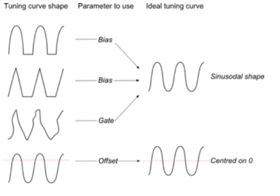
5. To tune channels manually, stop data acquisition and select Job / Manual tune in Tuner. Start changing the parameters of problematic channels little by little and check the effect. Recommended order of tuning is Gate, Offset, Bias. See the figure below for guidance.
6. Optionally, or for the nice finishing touch, you can run automatic tuning. From Jobs select Tune and hit Tune. Five minutes should be enough.
